Voltage Transformer Circuit Diagram
Cvt in electrical- circuit diagram, construction and working of Circuit supply power transformerless voltage circuits stabilized homemade make diagram electronic current simple schematic circuito projects capacitive diagrama dc led 4 simple transformerless power supply circuits explained
CVT in electrical- Circuit diagram, Construction and working of
14+ current transformer circuit diagram The electric online: transformer in voltage and current Transformer diagram working current secondary transformers power daenotes
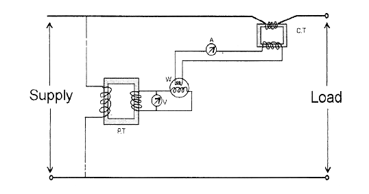
Direct and indirect measurements using cts and vts
Wiring diagram for current transformer with matching circuitTransformer current voltage measure use schematic circuit circuitlab created using diagram Current transformer circuit diagramTransformer circuit voltage power inductor equivalent model secondary current welder spot high iron parameters transformers open resistance vs side coupled.
Difference between current transformer and potential transformerTransformer electricalbaba equivalent Current transformerTransformer transformers electricalacademia.

Transformer wiring diagram explained : how to wire 3 phase
Types of transformers and their working with circuit diagramsTransformer current circuit potential diagram loaded Zoom electric blog: transformers- introduction and working principleTransformer transformers.
Transformer working principleCan i use a current transformer to measure voltage and current Transformer saturated neural estimationCurrent transformer circuit equivalent transformers power ct burden derivation.

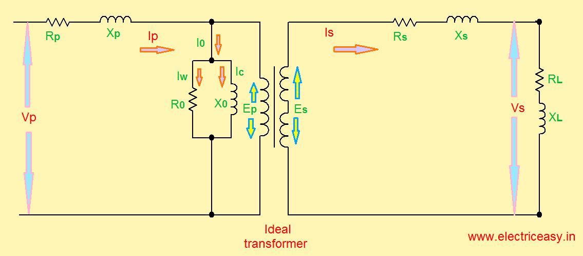
Equivalent circuit of transformer referred to primary and secondary
Transformer wiringCurrent transformer circuit diagram The essentials of current transformers in power circuits (theory andTransformers parameters.
Transformer winding wiring secondary connected windings connectionsCurrent transformer and potential transformer, circuit diagram, working Transformer working principleDiagram wiring vt voltage transformer direct measurements indirect cts vts using figure.
Transformer figure
Transformer current circuit diagram electric easy equivalent.ideal transformer circuit diagram 13+ single phase transformer circuit diagramVoltage transformer equivalent.
Power transformers transformer schematic voltages higher used high voltage currentTransformer works principle electricity voltage audio explain frequency Can power transformers be used with higher voltages?Transformer circuit equivalent primary secondary side referred parameters phasor form voltage electrical resistance reactance fig components ratio rated.

Current transformer wiring diagram collection
Transformer circuit working principle works electrical gif fig electricalacademiaElectrical topics: circuit diagram of loaded current transformer and Transformer circuit equivalent ideal side primary referred electrical principle working works fig quantities sameTransformer wiring diagram current phase ratio multi collection sample 5a faceitsalon.
Voltage transformer capacitor capacitive cvt electrical .


Transformers parameters - Electrical Engineering Stack Exchange

THE ELECTRIC ONLINE: Transformer in Voltage and Current
electrical topics: Circuit Diagram of Loaded Current Transformer and

Equivalent Circuit of Transformer Referred to Primary and Secondary

Current transformer circuit diagram | Download Scientific Diagram

Can I use a current transformer to measure voltage and current
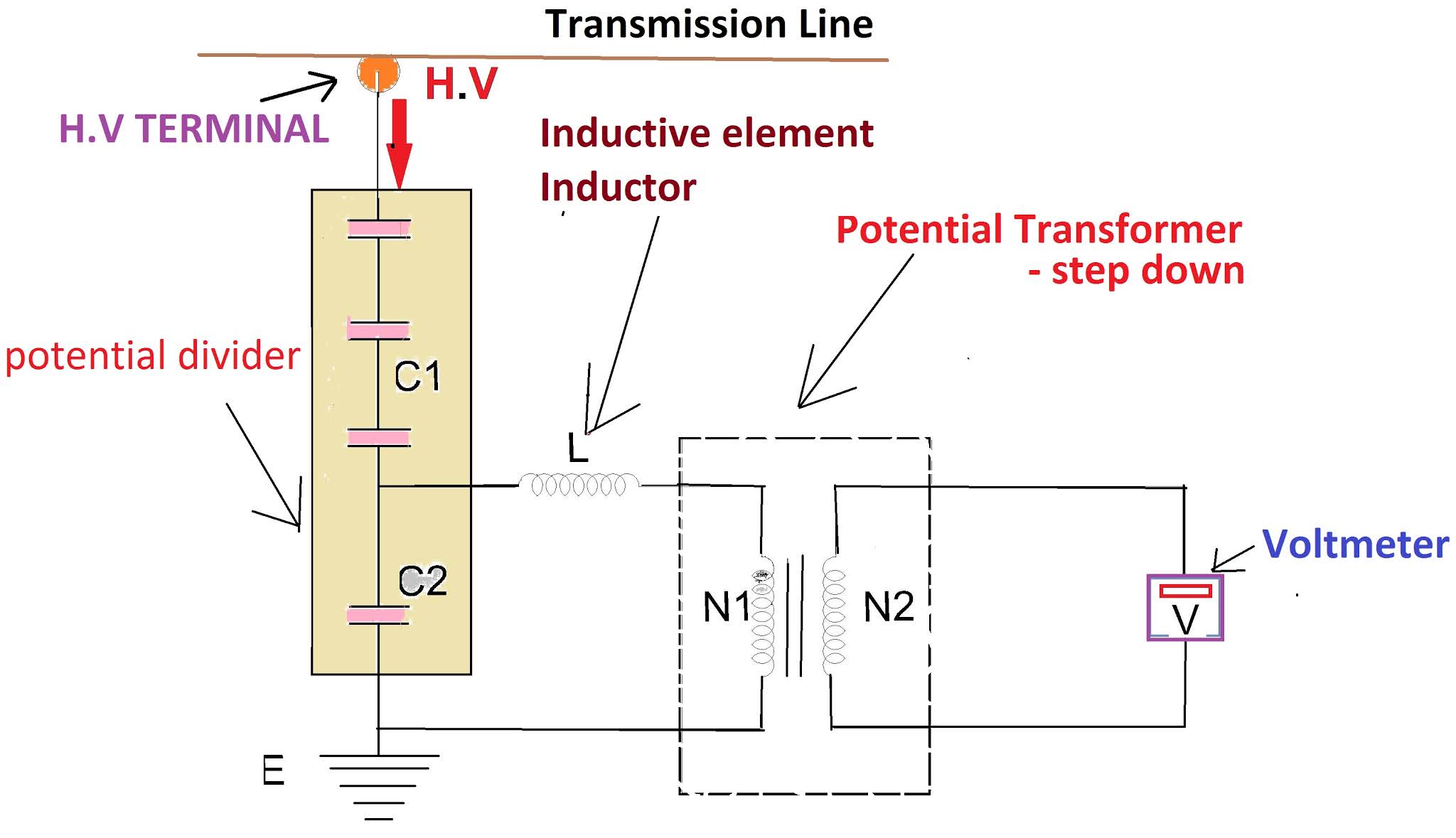
CVT in electrical- Circuit diagram, Construction and working of