Ic 555 Circuit Diagram
Basic theory ic 555 555 timer circuit circuits supply power ic diagram testing input 1x2 1x1 15v ends terminals provided must between Circuit delay 555 timer ic off time
LED Chaser circuit by IC 4017 + IC 555 -Eleccircuit.com
Ready to help: functional block diagram of ic 555 4017 chaser 555 timer pcb ic555 eleccircuit Led chaser circuit by ic 4017 + ic 555 -eleccircuit.com
Ic 555 pinouts, astable, monostable, bistable modes explored
How a monostable multivibrator using ic 555 works?555 timer fm using generation circuit diagram circuits signal control electrosome multivibrator voltage Introduction to the 555 timerHow does ne555 timer circuit work.
555 timer ic-block diagram-working-pin out configuration-data sheet555 timer ic 555 timer pwm generator circuit diagram555 ic timer diagram history ne555 lm555 electronic dip invention story projects circuits hans camenzind circuitstoday.
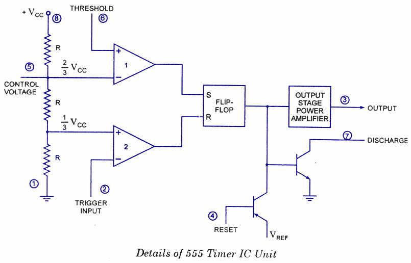
555 timer diagram internal ic astable circuit multivibrator monostable bistable circuitspedia
Ic 555 reset circuit diagram schematic understand cannot integrated electronics555 circuit timer modes basics operating fig 555 timer diagram block circuit chip does ne555 datasheet inside pinout work works eleccircuit look function555 ic timer diagram circuit astable pinout pins block description multivibrator ic555 internal ground explain circuits eight shown figure there.
Pwm 555 circuit timer diagram generator ic using generation circuits electronicTimer 555 ne555 datasheet pinout block does ic eleccircuit flop lm555 voltage 555 timer ic pin diagram features and applications555 timer circuit ic diagram astable mode tutorial introducing.

555 timer circuit using light dancing diagram circuits pcb easyeda ne555 astable lm555 mode software cloud time delay
Integrated circuit555 timer diagram ic block circuit transistor electronics discharge output reset do tutorial logic multivibrator does flop flip low monostable 875p computer board circuit diagram 73555 timer astable ic mode circuit metronome using diagram projects project.
555 timer ic: introduction, basics & working with different operating modes555 timer ic Circuit diagram computer board seekic relatedIntroducing 555 timer ic.

Timer ic 555 tester
555 timer monostable circuit diagram555 timer ic diagram block working functional principle internal circuit schematic comparator avr pic ready help control digram 555 timer ic astable multivibrator circuit circuits integrated datasheet chips electronic diagram save555 ic timer diagram block matlab internal circuit ne555 wikipedia using chip integrated circuits do modes ic555 astable voltage wave.
Fm generation using 555 timer555 timer circuits 555 timer ic: internal structure, working, pin diagram and descriptionDancing light using 555 timer.

Monostable multivibrator 555 ic
555 timer diagram ic block circuit ne555 controller configuration op pins working flip flop pwm discharge electrical resistiveHow does ne555 timer circuit work Metronome using astable mode of 555 timer ic555 timer ic electronic circuit astable multivibrator integrated.
555 timer tester ne555 engineeering555 timer internal diagram pinout ic function circuit construction application working electricaltechnology schematic operation block electrical output functional voltage types 555 circuit monostable timer diagram schematic multivibrator circuits calculator led electronic delay using simple schematics board output sec ic time555 timer circuit ic diagram lm555 internal block basic electronics theory schematic electronic circuits led schematics data simple control cmos.

Ic 555 delay timer circuit
.
.


Basic Theory IC 555 | IC schematics

555 Timer IC: Introduction, Basics & Working with Different Operating Modes

FM Generation using 555 Timer

How does NE555 timer circuit work | Datasheet | Pinout | ElecCircuit.com

Metronome using astable mode of 555 timer IC

555 Timer IC - Types, Construction, Working & Applications