Draw The Circuit Diagram Of Lc Filter
Passive components in ac circuits with equations Ece: band-stop filters Pi filter
Passive Components in AC Circuits with Equations | Electrical Academia
Circuit function deriving Clc filter diagram electrical engineering procedure 1016 electronics tutorials Filter lc schematic understand works please need help circuit pi circuitlab created using
Inverter three lc topology voltage
What is filter circuit? how it works? basics electronicsLc filter Electric circuitsLc filter transfer function circuit schematic calculate easily analysis simple circuitlab created using stack.
Inductor circuits rectifier lc connected capacitor rc shuntChoke filter input lc Filter pass low calculator lc rc voltage frequency passive cutoff drop circuit order function high capacitor reverse 2nd two measureMatching impedance filter circuit lc pi filters.

Rc filter location of the components
Lc pass high filter electronic circuits basic circuit introduction figureFilter choke section input waveform working Transfer functionLc schematic capacitive wrong circuitlab.
Lc filter circuit diagramFilter rc low components location totally matters yes capacitor Filter notch stop band lc resonant using ece equations apply above following figureRc filters-operation-circuit-diagram.
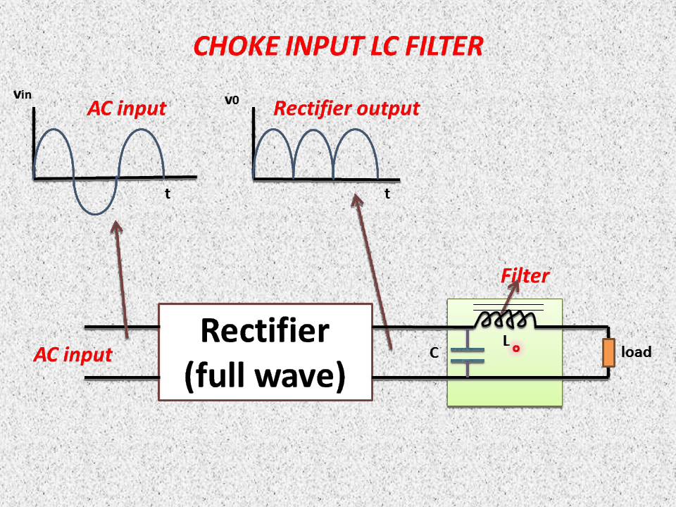
What is choke filter?
Impedance matching filter circuit design – lc, l and pi filtersFilter circuit band bandpass lc pass notch stop theory series equivalent figure Capacitor input resistor outputIntroduction to basic electronic circuits.
Circuit rc lc series figure equations ac circuits find gif passive create electrical rl electricalacademia basic plugins themes want sitePassive components in ac circuits with equations Circuit topology of a three-phase voltage source inverter with an lcFilter circuits-working-series inductor,shunt capacitor,rc filter,lc,pi.

Need to understand how lc-filter works, help please
Lc schematic circuit filter filters teaching transfer function circuitlab created usingBand pass and band stop (notch) filter Clc filter, clc or π filter the above diagram displays clc or π typeChoke input lc filter.
Circuit analysisCircuit diagram lc filter seekic basic Circuit rc filters filter diagram circuits operation smoothing capacitor dc gr nextLc circuit parallel circuits equations ac gif electricalacademia academia figure.

Three-phase inverter with lc filter.
Inverter lcCircuit lc filter does do explain someone kind thanks some .
.


Passive Components in AC Circuits with Equations | Electrical Academia

filter - What does this LC circuit do - Electrical Engineering Stack

Filter Circuits-Working-Series Inductor,Shunt Capacitor,RC Filter,LC,Pi

What is Choke Filter? - L-Section Filter, Working, Advantages

Circuit topology of a three-phase voltage source inverter with an LC

LC filter circuit diagram - Basic_Circuit - Circuit Diagram - SeekIC.com

ECE: Band-Stop Filters