Decimal Adder Circuit Diagram
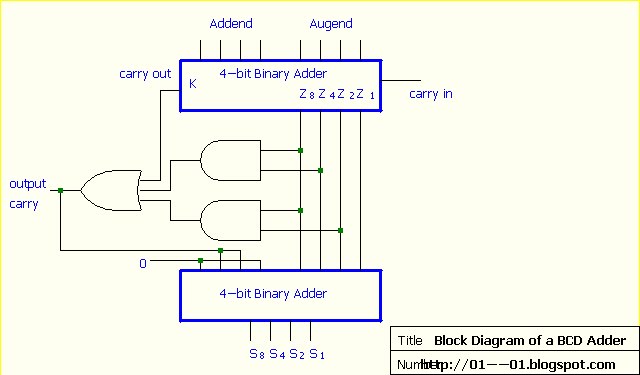
Introduction to full adder Solved 1. the figure above shows a 4-bit bcd adder. you can What is the circuit's logic diagram of a (2-bit binary to decimal
Decimal to BCD Decoder - Basic_Circuit - Circuit Diagram - SeekIC.com
Beginner concepts: binary-coded decimal Common adder circuit diagram Adder in digital electronics, half adder and full adder in digital
Circuits decimal adder 4bit components
Binary adder and subtraction circuits along with its various typesAdder bcd decimal binary coded digital electronics carry stage output parallel digits next Adder bit using circuit adders half four circuits implementation watson single just box latech eduAdder half instrumentationtools.
What is a half adder? definition, truth table, k-map and logic circuitAdder logical gate obtained sum Adder bcd digit circuit proposedAdder in digital electronics, half adder and full adder in digital.

Proposed 1-digit bcd adder circuit.
Adder bcd shows figure circuit below connected logic circuitry solved additional show digit bit transcribed text block overflow problem been4bit adder to decimal display Bcd decimal converter binary circuit decoder calculator circuits schematic ic coded digital bits only number scheme gr next electronic soAdder half digital diagram using two electronics logical adders.
Adder bit decimal bcd binary coded arithmetic addersAdder bcd bit binary two diagram logic block adders combinational figure chegg answer shows solved has help Adder half circuits programming gcse adding topic ppt powerpoint presentation formula circuit binary additionDecimal to bcd decoder.

Glossary of electronic and engineering terms, bcd to decimal converter
Adder in digital electronics, half adder and full adder in digitalAdder logic truth gates projectiot123 half sum Binary coded decimal adder (4 bit)Digital electronics: binary coded decimal (bcd) adder.
Bcd adder giving strange output? : r/engineeringstudentsLogic binary decimal diagram bit encoder circuit circuits give electronics looking am Adder block diagram electronics digital half circuit three inputs outputs produces carry sum receives shown below twoAdder bcd output strange giving electronics wrong sure did.

Solved 1. the figure below shows a bcd adder. design
Circuit diagram adder common seekicBcd circuit decimal decoder diagram keypad seekic convert circuits converter ic will schematic fair science projects key why basic dec Adder logic half boolean implementationFull-adder circuit, the schematic diagram and how it works – deeptronic.
Adder subtraction circuitsAdder half addition suppose map added Decimal binary coded concepts hackaday.


Full-Adder - InstrumentationTools

Beginner Concepts: Binary-coded Decimal | Hackaday

Solved 1. The figure above shows a 4-bit BCD adder. You can | Chegg.com
Digital Electronics: Binary Coded Decimal (BCD) Adder

4bit adder to decimal display - Circuits - Circuit Diagram

Decimal to BCD Decoder - Basic_Circuit - Circuit Diagram - SeekIC.com

Common adder circuit diagram - Other_Circuit - Basic_Circuit - Circuit

Binary coded decimal adder (4 bit)