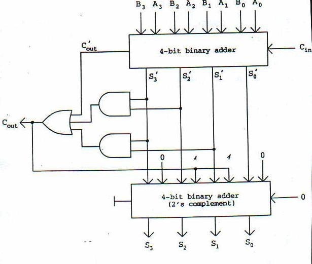
4 Bit Binary Adder Circuit Diagram
Adder bit using circuit adders half four circuits implementation watson single just box latech edu Digital logic Binary adder circuit / circuit additionneur binaire
11+ 4 Bit Adder Circuit Diagram | Robhosking Diagram
Half adder / full adder Cd4008 4-bit full adder ic pinout, working, example and datasheet Let's learn computing: 4 bit adder/subtractor circuit
Verilog code for bcd adder
Adder bit subtractor circuit ripple carry diagram logic using project build only digital computing learn let its single indie electronicsAdder half bit mediawiki online binary numbers number together index Binary multiplierDigital logic.
Adder alu nor nandAdder binary bit circuit rtl truth table example understand will need register adders use discuss details Adder subtractor bit circuit add sub questions overflow complement logic detection carry addition designing control zero line digital findAdder bcd bit binary two diagram logic block adders combinational figure chegg answer shows solved has help.

Adder subtractor binary circuit bit diagram coa logic block javatpoint mode
Adder additionneur binaire zpag electroniques gate sum11+ 4 bit adder circuit diagram Make adder subtractor bit carry ripple verilog binary using 4bit want subtraction addition operation output hdl which has valueAdder logisim bit circuit binary.
Adder circuit gate adders implement expressions two😊 four bit parallel adder. 4 bit binary adder circuit / block diagram Using bit half adders four circuit logic digital schematic circuitlab created electronics4 bit binary adder.

Cs 3410 spring 2018 lab 1
Adder truth logic half sumador gates binario inputs datasheet combination suma microcontrollerslabFull-adder circuit, the schematic diagram and how it works – deeptronic Adder binary parallel bit logic diagram circuit electronics betweenSolved 1. the figure above shows a 4-bit bcd adder. you can.
Multiplier bit binary using multiplication adders schematic calculator divider digital 4x4 adder logic gates electronics electricaltechnology possible electronic multipliers types4 bit full adder circuit, truth table and symbol. implement 4 bit Adder bit logisim using circuit complement alu cs unsigned lab1 lab labs courses cornell edu build create re ta sub4-bit binary adder-subtractor.

What is parallel binary adder?
Adder subtractor bit binary alu if gates chapter performs ppt powerpoint presentation programmable inverters xor actN-bit binary adder circuit by logisim Adder circuit diagram schematic bit works figureAdder bit four diagram parallel block ripple carry circuit binary.
Bcd adder verilog .


digital logic - 4-bit decrementer using four Half Adders - Electrical

Verilog Code for BCD Adder

PPT - Chapter 6-1 ALU, Adder and Subtractor PowerPoint Presentation

11+ 4 Bit Adder Circuit Diagram | Robhosking Diagram

😊 Four bit parallel adder. 4 bit Binary adder circuit / block diagram

What is Parallel Binary Adder? - 2-Bit and 5-Bit Parallel Binary Adder

COA | Binary Adder-Subtractor - javatpoint

digital logic - Designing a 4-bit adder-subtractor circuit - Electrical