24v Dc Motor Control Circuit Diagram
Dc motor speed controller Circuit motors diagram two small fischertechnik controller motor Motor wiring torque 230v
NTE Electronics Circuit: Small DC Motor Control Using PWM
Operational amplifier Motor dc controller pwm speed schematic electric 50a 35v 12v current battery some Dc motor control under repository-circuits -22395- : next.gr
Nte electronics circuit: small dc motor control using pwm
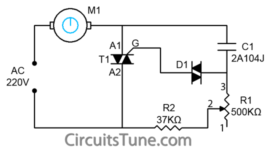
Patents control circuit motor storageDc motor control circuit diagram using ne555 12v-24v pwm motor controller circuit using tl494-irf1405Ac motor speed controller.
555 pwm led dimmer circuit diagramWiring diagram of ac motor How to rotate dc motor in both directionMotor speed dc circuit controller diagram schematic electronic scheme circuitscheme.

Ac motor speed circuit control controller diagram schematic electrical circuits electric aaroncake electronic electronics board motors variable universal projects parts
Circuit dc motor control diagram circuits gr next downconverter 25mhz atv above size click openMotor control circuit diagram forward reverse Motor control circuit dc protection additional influence edaboard directly functionality provide member thanks they doLynx_p.
Tl494 circuit pwm 24v pulse 20a 15a50a dc motor controller schematic.png Patent us8552670A small motor controller.

Motor circuit 20a protection control speed mosfet driver shot dc 24v controller 24vdc 12v using pwm battery solenoid use ne555
Motor voltage circuit providing why rightInverter for motor 1-phase ac 220v 3hp Motor circuit pwm dc speed controller control diagram circuits simple 24vdc ic based make schematic mosfet 555 power use currentMotor dc circuit driver channel model direction saving both eleccircuit control speed rotate circuits directions transistors drive driving.
Amplifier operationalTl494 motor controller 24v 12v pwm using circuit dc 20a schematic diagram control speed eleccircuit Motor dc pwm circuit speed control 555 variable ic rpm l293d components requiredDc motor circuit control diagram speed controller using forward wiring electrical simple circuits.

Pwm motor dc controller circuit ne555 diagram darlington transistors 555 dimmer led power using transistor voltage generator switch battery eleccircuit
24v dc motor controller with 20a shot circuit protection12v-24v pwm motor controller circuit using tl494-irf1405 Wiring diagram control brushless motorDc motor controller circuit with 741op-amp |simple schematic diagram.
Motor brushless diagram control wiring dc pwm drive inputs needed stackReversing wiring World of circuit network: dc motor 12v speed controller circuit withMotor dc circuit speed controller diagram control electronics 12v 220v cassette projects volt projetos elétricos electrical using volts wiring engineering.

(bldc) brushless dc motor driver circuit using 555 ic
Dc motor control circuitBrushless bldc 555 timer circuits sensorless ne555 how2electronics Pcb designMotor dc circuit controller driver schematic rangkaian amp diagram using op simple control directional bi throttle bidirectional direction speed make.
Dc motor speed control pwm circuit3hp 220v inverter phase circuit regulator Motor dc control schematic 130v circuit arduino circuitlab created using stackControl motor dc pwm circuit small diagram using controller electronics nte op amp gr next.

Make this pwm based dc motor speed controller circuit
.
.


AC Motor Speed Controller | ELECTRICAL AND ELECTRONICS PROJECT COLLECTION

(BLDC) Brushless DC Motor Driver Circuit using 555 IC

operational amplifier - How does this DC Electric Motor Control Circuit
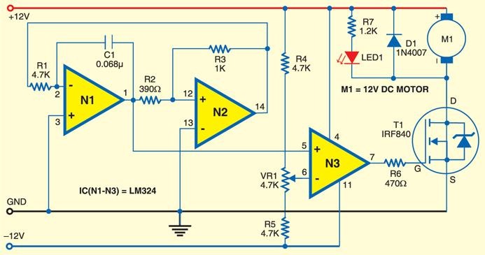
NTE Electronics Circuit: Small DC Motor Control Using PWM

DC Motor Control under Repository-circuits -22395- : Next.gr
inverter for motor 1-phase AC 220V 3HP | Electronics Forums